Reading & Interpreting Hydraulic Schematics for Pumps & Motors
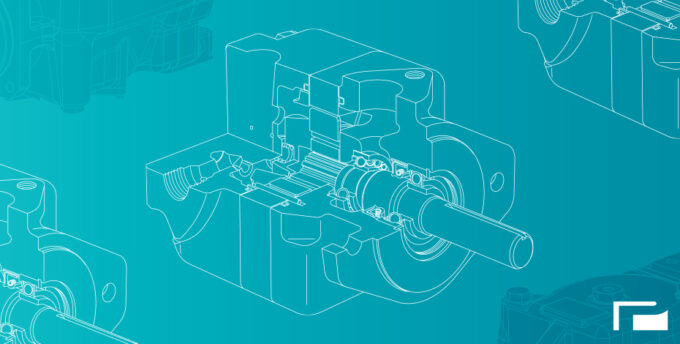
Schematics are the blueprint for constructing, troubleshooting, and maintaining hydraulics systems. If you know you’re regularly going to be working with these systems and you’re not sure how to read and interpret these diagrams, you’ll need to learn. Otherwise, you won’t be able to properly set up your system or predict or troubleshoot potential issues.
In this blog, we’ll discuss how to specifically read pump and motor symbols within schematics and how to interpret their relevant path flows.
Pump Schematic Symbols
The universal symbol for a hydraulic pump is a circle with a triangle inside. The triangle indicates the direction of flow.
However, schematics may also include more specialized symbols for different pump types, including:
- Gear Pump: Shown as a pair of meshing gears within a circle.
- Piston Pump: Represented by a circle with one or more vertical or diagonal lines inside.
- Vane Pump: Depicted as a circle with a radial line or arrow that indicates the rotating vane mechanism inside the pump.
- Screw Pump: Illustrated with a profile that resembles interlocking screw threads.
- Fixed Displacement: This will be shown as a circle with an internal gear symbol (or another symbol, such as vertical lines, diagonal lines, radial lines, screw threads, etc., that don’t have any arrow indicating adjustability).
- Variable: This will be shown as a circle with the same internal symbols as fixed pumps but with the addition of an arrow across the circle or alongside the pump symbol.
The schematics will also have specifications to help with quick interpretation or analysis. These include:
- Q: The flow rate of the pump
- P: Pressure or pressure rating
- ΔP: Pressure differential
- → or 1: Flow direction
- Max P: Maximum operating pressure.
- N: Rotational speed in revolutions per minute.
Motor Schematic Symbols
Like hydraulic pumps, there is a universal symbol for motors in schematics, which is represented by a circle with a cross inside.
More specifically, you may see symbols for gear, piston, and vane motors. Gear motors are depicted similarly to gear pumps with gears inside of a circle with an external arrow to show rotational direction.
Piston motors are shown in one of two ways: 1) a circle with several lines radiating from the system towards the edge, illustrating that it’s an axial piston motor, and 2) a circle with several small circles or dots within it, arranged in a circular pattern around the center, which indicates that it’s a radial piston motor.
Lastly, vane motors are shown with a radial line or slotted rotor inside a circle.
Other specifications or notations you may see related to hydraulic motors include:
- D: Usually, this is noted beside the motor symbol. It indicates volumetric displacement.
- Max P: Similar to pumps, this specifies the maximum operational pressure the motor can handle.
- N: This indicates the maximum or operating speeds (RPM) of the motor.
Other Hydraulic Symbols
- Check Valves: Depicted as a ball within a titled seat, indicating that fluid can only flow in one direction.
- Pressure Relief Valves: Shown as an arrow on a seat.
- Accumulators: These are symbolized as a circle with an internal diagonal line.
- Filters: These are diamond-shaped.
- Coolers & Heaters: These are illustrated with a coil or radiator symbol.
- Reservoirs: Shown as a rectangle, usually with a horizontal line to indicate the fluid level.
How to Interpret Flow Paths
Interpreting the fluid flow path is actually pretty simple. Schematics will feature flow lines (solid or dashed lines), which represent the path that the fluid takes throughout the system. Solid lines indicate working lines, while dashed lines usually represent pilot or drain lines.
Within the flow lines are connection points, usually depicted as arrows to show the entry and exit points of the fluid within the pumps and motors.
There will also be arrows on the flow lines, which symbolize the direction in which the fluid is moving. The arrow pointing towards a pump refers to the fluid entering the pump, while the arrow pointing away from the motor indicates fluid exiting the motor.
Learn More From Panagon Systems
Founded over 25 years ago, Panagon Systems is an industry-leading U.S. manufacturer of aftermarket hydraulic pumps and motors serving businesses worldwide. Please visit our blog for more informational resources.


