The Role of a Gerotor in a Hydraulic Pump

A gerotor is an internal gear set that converts shaft rotation into steady fluid flow with compact packaging and low noise. At Panagon Systems, we focus on precision manufacturing and replacement of these components so our customers can restore performance in legacy equipment and keep operations running. The role of the gerotor in a hydraulic pump is to draw fluid from the inlet, trap it in expanding chambers, and deliver it to the outlet at controlled volume per revolution. Everything about pump output, efficiency, durability, and noise begins with how well the gerotor is designed, machined, finished, and matched to its housing.
What a Gerotor Is and What It Does Inside the Pump
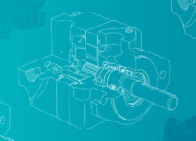
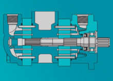
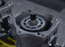
A gerotor consists of an inner rotor with n teeth and an outer rotor with n+1 teeth. The outer rotor is offset from the inner so the chambers formed between the tooth profiles expand on one side and contract on the other as the set turns. Expansion on the inlet side creates suction that fills the chambers with hydraulic fluid. Contraction on the outlet side compresses the volume and discharges fluid into the pressure port. Because the geometry repeats each revolution, the displacement is fixed by the chamber volume and the number of chambers that pass the outlet per turn. This makes gerotor pumps predictable, simple to control, and suitable wherever a consistent flow per rpm is required.
The gerotor element is supported by bearings and runs with controlled clearances against side plates and the housing. Proper end clearance and side leakage control are essential to volumetric efficiency. The element also relies on internal lubrication from the working fluid. Surface finish, tooth form accuracy, and material hardness determine how quickly a new set seats in and how well it resists wear over long duty cycles. When a gerotor is manufactured with tight tolerances and installed in a clean, well aligned housing, it delivers smooth flow with minimal ripple and low acoustic signature compared to many external gear designs.
How the Gerotor Turns Rotation Into Flow and Pressure
The pump shaft is keyed or splined to the inner rotor. As the shaft rotates, the inner rotor drives the outer rotor through tooth contact, maintaining the phase relationship that creates expanding and contracting pockets. Flow is fundamentally a volumetric phenomenon. The displacement per revolution is the sum of the pocket volume changes across all chambers. Pump output flow equals displacement times speed, minus leakage. Leakage occurs across tip clearances, side clearances, and any internal balancing features. Mechanical and volumetric efficiencies describe how much input power is lost to friction and how much potential flow is lost to leakage. Good gerotor sets keep those losses low by holding clearances stable across temperature and pressure.
Pressure arises because the outlet chambers shrink while resisting the downstream load. The element does not create pressure by itself. It creates flow against a restriction, and the system develops pressure accordingly. For that reason, system relief valves and compensators protect the pump from overpressure. The gerotor’s tooth profile and port plates must manage trapped oil as chambers pass the sealing line. If trapped oil cannot vent, pressure spikes can occur that raise noise and stress the tooth flanks. Correct port geometry, edge breaks, and micro reliefs allow residual volume to equalize and reduce pressure pulsation.
Fluid properties strongly influence performance. High viscosity improves sealing and reduces slip at low speed, but excessive viscosity raises starting torque and heat at cold start. Low viscosity eases cranking but increases leakage at temperature. A gerotor pump should be selected and clearanced for the expected viscosity range so it starts reliably in cold conditions and maintains efficiency when hot. Inlet conditions matter as well. The expanding chambers create suction, so the inlet must be short, unrestricted, and flooded with clean fluid to prevent cavitation. Cavitation damage appears as pitting and spalling on tooth flanks and side plates, which increases leakage and accelerates wear.
Design Variables That Set Displacement, Efficiency, and Life
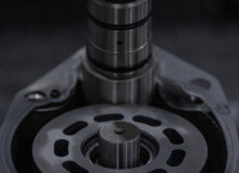
Several design parameters define how a gerotor performs. Tooth count and eccentricity set the displacement and the number of discharge events per revolution. More chambers can smooth flow and reduce pulsation, but may raise sliding losses if not balanced with proper clearances. Tooth profile accuracy and conjugacy ensure that contact stress is distributed and that sliding velocities remain manageable. Side plate flatness and parallelism control end leakage and also act as thrust surfaces that stabilize the set at pressure. Material selection and heat treatment determine strength and wear resistance. Hardened alloy steels with controlled case depth and fine surface finish are common in demanding industrial duty.
End clearance is a critical setting. Too tight and the set runs hot and may seize during thermal growth. Too loose and volumetric efficiency drops. We machine and measure components so end clearances land in a narrow band when assembled at room temperature and remain within specification across the operating temperature range. Runout control on the drive shaft and precise concentricity between the bore, pocket, and port features prevent uneven tooth loading and premature bearing wear. Port plate geometry shapes flow into and out of the chambers. Gentle lead-in and lead-out angles reduce pressure ripple and noise, while properly sized kidney ports prevent throttling losses at high speed.
Installation details also affect real-world results. Mounting orientation influences case fill and lubrication to the bearings. A flooded inlet and correct case drain routing help carry away heat and air that would otherwise degrade efficiency. System filtration protects the close-fitting surfaces of the tooth flanks and side plates. Clearance sized for clean oil can be ruined quickly by abrasive contamination. Selecting filter ratings to hit target cleanliness levels and placing filters where they see the right flow direction preserves the seal line between the rotors and the housing. Finally, drive coupling alignment prevents radial loads that can tilt the set and open up one side clearance, which shows up as rising case temperature and noise.
Reliability, Failure Patterns, and Service Practices
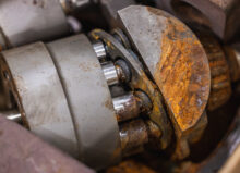
Most gerotor issues trace back to contamination, poor inlet conditions, misalignment, or running outside the intended viscosity and pressure envelope. Abrasive particles score the side plates and tooth flanks, increasing internal leakage and reducing volumetric efficiency. Aeration or cavitation pits surfaces and produces a whine that worsens with speed. Misalignment or bent shafts create cyclical contact patterns and lead to accelerated bearing and seal wear. Excessive pressure without adequate relief protection can cause scuffing, spalling, or tooth root cracking in extreme cases.
A structured maintenance approach keeps the element in service longer. Start with oil condition. Track viscosity at operating temperature and keep cleanliness within a specified ISO code. Replace filters on differential pressure rather than on calendar time so you know you are maintaining capture efficiency. Monitor case temperature and pump noise as early indicators of clearance drift or inlet problems. During service, inspect tooth flanks for uniform contact patterns, check side plates for flatness and wear tracks, and measure end clearance during rebuilds. Replace seals and bearings as a set when you replace the gerotor element so the assembly returns to baseline performance.
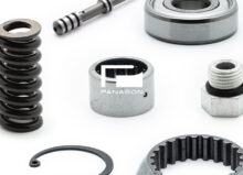
When a pump is down, parts availability and interchangeability matter. We produce replacement gerotors and kits to restore function in legacy units where original equipment parts are scarce. That includes matching tooth counts, profiles, and critical dimensions so the rebuilt pump drops into the existing housing and interfaces. We verify fit and function with dimensional inspection and controlled test stands, checking flow versus speed and leakback at pressure to confirm that volumetric efficiency meets target. For customers looking to upgrade performance, we can advise on changes to displacement, porting, and clearances that improve cold starts, reduce noise, or increase throughput within the limits of the existing drive and downstream components.
Contact Us Today
The gerotor is the pumping core that sets a hydraulic pump’s displacement, smoothness, and efficiency. Its geometry defines how much oil moves each revolution, its clearances and finishes determine how much of that oil becomes useful flow, and its materials and profiles drive how long it holds those numbers in real production environments. Reliable operation depends on clean fluid, proper inlet conditions, correct end clearances, and sound installation practices. When you need to restore a pump, match a displacement, solve a noise or efficiency problem, or source replacement gerotors and kits for legacy equipment, contact Panagon Systems. We can help you identify the correct parts, validate fit and performance, and return your system to dependable service. Contact us today!